
Featured Project Return to Projects List
Rikers Island Chiller Plant and Tunnel Work
Project Information
- Project Location:
- Elmhurst, NY
- Approx Contract:
- $500,000
- Status:
- Completed - Aug 2017
- Structure Type:
- Jail / Prison
References
- Owner:
- NYC Dept. of Justice
- Architect:
- NYPA
- General Contractor:
- Dynamic Energy Inc.
- Client:
-
Biping
Patel
-
Vice President
(201) 289-5692Dynamic Energy, Inc
Scope Of Work
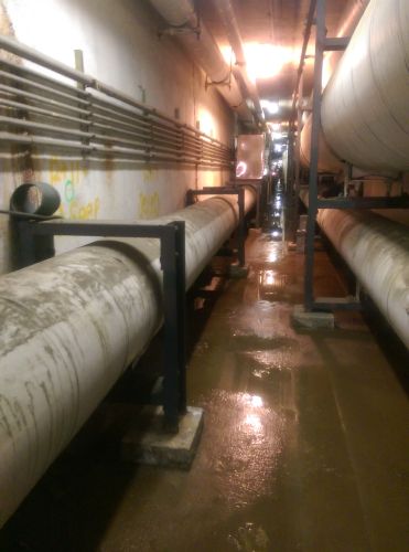
Our contract was to install 1600 lf of a prefabricated chilled water piping system and install it in an existing steam tunnel. The carrier pipe was 14" schedule 40 butt weld joints. Our responsibilities also included layout all piping sections for offsets and elevation changes for fabrication. Pipe supports and hanger design was also part of our scope of work.
This project was one of the most challenging pipe fitting and welding projects we have ever undertaken. 1600 Ft. of twenty foot sections of 14" double wall piping with an OD of 18" with a weight of 1800 lbs per section. There was only one access to bring the pipe in the tunnel. This was the first obstacle. The point of entry was through an 18' sea box burried in the ground on top of the steam tunnel. This was the longest sea box that could be buried because of existing inderground utilities. There was a hole cut in the bottom of the sea box and a hole cut in the top of the steam tunnel. These holes were 17 L' x 36 W. Three foot shorter than the length of the pipe sections.
The next obstacle was bringing the pipe down the length of the tunnel to the place of installation. The width of the tunnel was at it narrowest location was 20" wide with the average width of the tunnel being 30" wide. We had to fabricate a set of pipe dollies to roll the pipe down the tunnel. We chose and automotive dolly and modified it with heavy duty swivel caster to accommodate the weight of the pipe. Each of these dollies could carry 3000 lbs. More than enough to safely carry the pipe to it's location for installation. Two of these were used , one on each end of the pipe sections, to move the pipe down the tunnel.
The third obstacle was a 26 degree mitered turn in the tunnel. The pipe was too long to make the turn on the ground with such a narrow passage. We constructed a rail system on the ceiling to make the turn in the tunnel with the 20' sections of pipe. This rail system we designed was constructed of two I beams. One on each side of the miter. A series of beam trollies were installed on the I beams to move the pipe around the corner as well as a motorized lifting system to get the pipe in the air and rigged to the rail system.
The next obstacle was the welding of the sections of pipe. The pipe design was so close to the wall and one pipe over the top of the other made it near impossible to weld in position. We needed the ability to roll up to 400 lf of straight sections of pipe at a weight 36,000 lbs in order to expedite the welding and assure quality welds could be made on the pipe joints. After consulting with expert engineers in the pipe handling and welding machinery fields, they could not come up with a cost effective way for us to use any industry standard equipment for our project. We came up with a simple cost effective solution to the problem. We used the same swivel casters we used for the pipe dollies we fabricated to move the pipe welded on a piece of flat bar. We laid these assemblies on top of an existing channel support to roll the pipe with a simple series of chain blocks to easily roll the pipe. The construction management firm, Not to be named, was so impressed with our solution to the welding problem that they took credit for our design.
This project was completed to great satisfaction by all involved.
Project Images


